
Function and task of electro-pneumatic switching valves:
In modern motor vehicles, electro-pneumatic switching valves, also known as electro-pneumatic converters, play an essential role in the efficient and precise control of various systems. These valves act as a link between electronic controls and pneumatic components by converting electrical signals into pneumatic actions. This makes them indispensable for regulating negative pressure in systems such as turbochargers, EGR valves or swirl flaps/switched intake manifolds.
The main task of an electro-pneumatic switching valve in the automotive sector is to precisely control the air flow based on the instructions from the vehicle control unit. The electronic control allows the valve to switch quickly and accurately between different states, which is crucial for the responsiveness and efficiency of the vehicle
The valve consists of an electrical part that acts as an actuator and a pneumatic part that controls the air flow. When the vehicle’s control module sends an electrical signal to the valve, the actuator moves a diaphragm or piston to open, close or regulate air flow.
Check possible errors:
Optical visual inspection:
- Tools/Aids: Flashlight
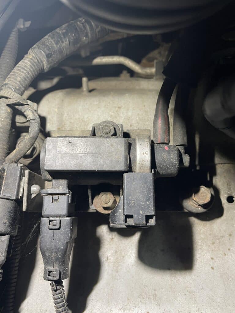
- Inspection: The first thing you should always check is whether the valve is visually in perfect condition. In particular, you should pay attention to whether the two connections on the valve to which the vacuum hoses are plugged are still intact. The two connections are mostly made of plastic and relatively thin. Over time, exposure to heat and heat causes the plastic to become porous and can break.
Of course, the plug or electrical connection should also be checked to see if there is any damage.
During the visual inspection, special attention should be paid to abrasions and kinks on the cable itself. Also check whether the insulation of the cable is still completely intact. When connecting the plug, the plug must be unplugged. Now you can look into the connector housing itself to check whether the “PINs” are still OK. Special attention should also be paid to whether there are traces of oxidation (reaction of aluminum/metal with water or other liquids) in the plug.
If traces of oxidation can be seen, the first step should be to check the seal of the plug housing itself to see whether it is undamaged, as this is usually the main problem for oxidation damage.
If the seal is undamaged, the liquid can also come from the component that the plug is connected to, like from the thermostat or from a temperature sensor. In this case, the component itself must of course be replaced.
Checking the electrical connections Resistance measurement/voltage test:
- Tools/aids: circuit diagram, multimeter
- Testing: Using the resistance measurement, you can also test whether the cable connection is still OK, just like with the voltage test. However, the cable connection can be tested more precisely here. (To see detailed instructions for this test, click here)
Functional test of the valve:
- Tools/Aids: Measuring adapter/measuring tips, external power supply
- Test: This test can be used to determine whether the valve is still working electrically. This requires thin measuring tips or measuring adapters that can be plugged into the two PINs of the valve and an external power supply that can provide 12V. The disconnected vehicle battery can also be used as an external power supply.
Once the cables are connected to the valve, only the other two ends of the cables need to be held at plus and minus. If you hear a click/clack, the valve is working. If nothing is heard, the valve is defective.
Valve resistance test:
- Tools/aids: Multimeter, thin measuring tips/measuring adapter
- Test: During this test, the valve itself or the coil inside is checked for resistance.
As a rule, these valves are connected with cables. In order to carry out the test, the wiring harness/plug must first be disconnected from the valve. Now you can see two PINS on the valve itself to which the multimeter must be connected using measuring adapters. If the multimeter is connected, it can be set to “resistance test or continuity test Ω” and switched on.
During this test the valve should be OK and a resistance value of 10-20 Ω should come out. For valves that are available from the accessories trade, the resistance can also be up to 40 Ω.
However, if the test shows low resistance or “OL Open-Line” is shown on the multimeter display, the valve is defective and should be replaced .