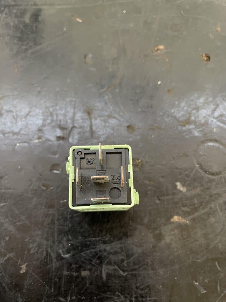
Function and task of an electrical relay:

Electrical relays play an essential role in how modern vehicles function. These small but powerful components serve as a critical interface in a car’s electrical circuitry. A relay basically works like an electrical switch, allowing one circuit to be controlled by a lower current in another circuit. This is particularly useful in situations where a small signal must be used to switch a larger load, such as when starting the engine or turning on the headlights.
The primary job of a relay in a vehicle is to safely switch large amounts of current without damaging switches or other components designed for lower currents. Thanks to their ability to control high currents, relays make a crucial contribution to ensuring the longevity of electrical components in the car and increasing safety.
By using a relay, for example, the vehicle’s headlight switch can be implemented with a relatively small and easy-to-use switch, even though the headlights themselves require a much higher current. This reduces the load on the switch and reduces the risk of an electrical fault.
“Normally closed or normally open relays” are most commonly used in motor vehicles.
In its most basic form, this relay works as a simple switch. This connects terminals 30 and 87, allowing current to flow between these two points when the relay is activated. This causes the circle to close. Conversely, if the relay is deactivated, this circuit is interrupted. This type of relay is often referred to as a Normally Open (NO) relay because the circuit is open when resting. There is also the reverse variant, known as Normally Closed / normally open relay” (NC), in which the circuit is closed in the idle state and opens when the relay is activated.
Relays are installed in various systems in the car, with one of the best known relays being the fuel pump relay or the turn signal relay. Of course, there are also other systems in which relays are installed, such as: E.g.:
- Headlight: To turn the low beam on and off
- Air conditioning: For controlling the air conditioning compressor
- Starter relay: To control the start of the engine
In practice, this means that a defective relay can cause problems in the corresponding function of the car, be it starting the engine, operating the headlights or other electrically controlled functions. Therefore, it is crucial to know the location and condition of the relays in the vehicle and to check them regularly to ensure the smooth functioning of all electrical systems.
Installation location:
As a rule, relays are always installed near the fuse box or near the vehicle battery. Many more modern vehicles also have a fuse box in the trunk and in the engine compartment.
In some cases, relays are also integrated into control devices, which means that they can neither be tested nor replaced individually.
Checking the relay:
Optical Visual inspection of a relay:
- Tools/aids: occupancy plan/operating instructions, flashlight
- Testing: To determine whether a relay is defective during a visual test, the relay must be removed from its socket in the relay box. Once the relay is removed, you can use a flashlight to check for any signs of damage such as burns, cracks, or other obvious defects on the relay body or terminals. Additionally, you can also look for signs of corrosion or wear on the connection points, which could indicate potential malfunctions.
Continuity test:
- Tools/aids: assignment plan/operating instructions, multimeter
- Test: This test can be used to determine whether the relay is still conducting electricity internally in the case of a normally closed relay or whether it is not conducting current in the case of a normally open relay.
In order to be able to carry out this test, the relay must be set to the “continuity test/resistance test”.
Normally open relay: The measuring tips of the multimeter must be held on the connections 30 and 87 of the relay (the terminal designations of the relay are usually described next to the connections). Now the multimeter should display the value “OL Open-Line” or not beep. So the relay is OK.
Normally closed relay: The measuring tips of the multimeter must be held on connections 30 and 87 of the relay (the terminal designations of the relay are usually described next to the connections). Now the multimeter should beep or show a very low resistance value (0-1 Ω), if this is the case the relay is OK.
Resistance measurement:
- Tools/aids: assignment plan/operating instructions, multimeter
- Test: This test can be used to determine whether the resistance in the relay coil is still OK. Here too, the multimeter must be set to resistance. Now hold the measuring tip on the contacts of terminals 85 and 86. In general, one can say that the nominal value for relays for cars should be between 50 – 120 Ω. However, the exact resistance value differs depending on the manufacturer of the relay and the intended use.
Functional test using an external power source:
- Tools/Aids: Multimeter, external power source (9-12V)
- Test: This test can be used to determine whether the relay is still switching and can therefore work properly. An external power source such as B. requires the vehicle battery or a 9V battery. In the first step, terminals 85 and 86 must be supplied with power so that a closed circuit is created. You should now hear the relay click. The red cable of the multimeter must now be connected to terminal 30 and the black cable to terminal 87. A low resistance value should now be visible for a normally open relay and the “open line” value for a normally closed relay.
(This video shows how to test a relay with an external power source)

