In the complex world of vehicle technology, cables, connectors and cable harnesses play a crucial role. They are the nervous system of every vehicle through which information and energy flow. Cables are the fundamental connecting lines that transmit electrical energy and signals between various components of a car. They ensure that everything from the lighting to the audio system to the engine control functions properly. Connectors serve as connection points that enable flexible assembly and maintenance of these systems. They make it possible to quickly connect or disconnect components and thus contribute significantly to the efficiency of vehicle maintenance.
Wiring harnesses are, in turn, the organized networks of these cables and connectors, tailor-made for each vehicle model. They bundle several cables into a single, clear strand that is specially designed to fit perfectly into the vehicle architecture. This bundling not only makes installation and maintenance easier, but also helps minimize interference and electromagnetic interference.
The proper functioning of these components is essential to the safety and efficiency of the vehicle. Damage, whether due to wear and tear, accidents or other influences, can lead to a range of problems, from simple malfunctions to serious safety risks. It is therefore crucial to identify and eliminate possible sources of error at an early stage. This requires a systematic approach to ensure the integrity and performance of the vehicle’s electrical system. In the following sections, we will look at how to effectively locate and inspect damaged cables, connectors and wiring harnesses in a car to ensure the vehicle’s functionality and safety.
Checking a cable connection/plug connection:
Optical visual inspection:
- Tools/aids: circuit diagram, flashlight
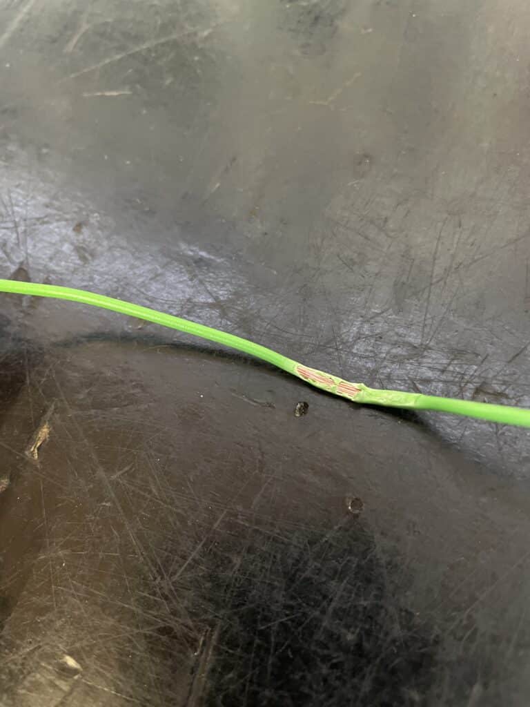
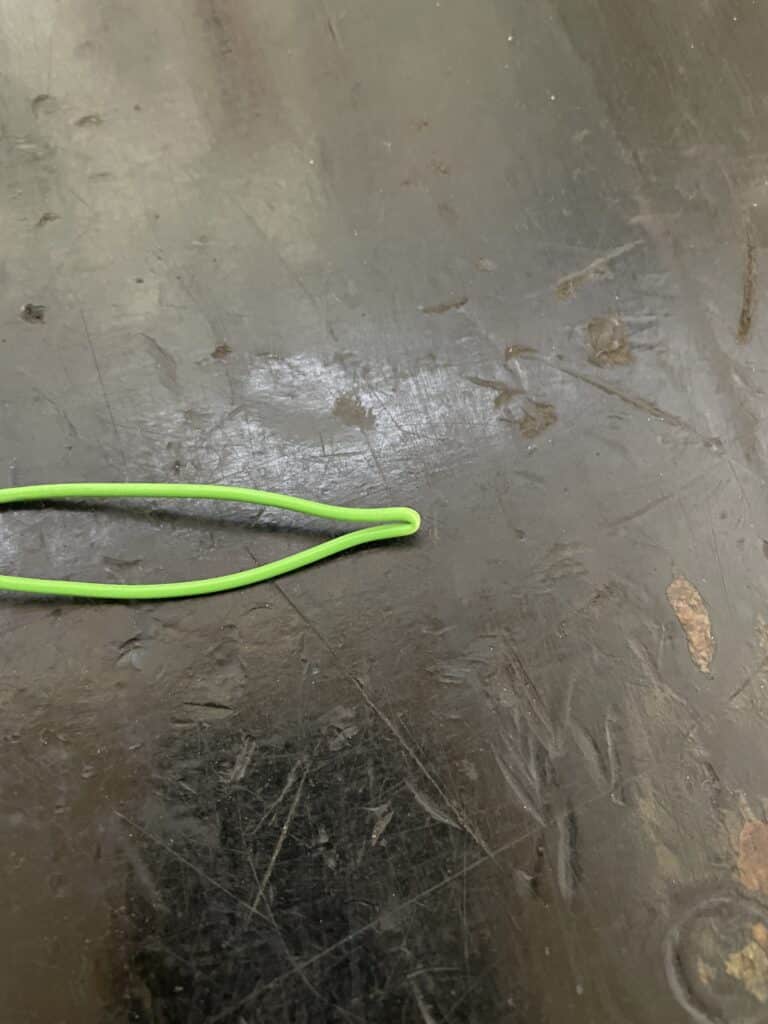
- Inspection: During the visual inspection, special attention should be paid to abrasions and kinks on the cable itself. Also check whether the insulation of the cable is still completely intact. When connecting the plug, the plug must be unplugged. Now you can look into the connector housing itself to check whether the “PINs” are still OK. Special attention should also be paid to whether there are traces of oxidation (reaction of aluminum/metal with water or other liquids) in the plug.
If traces of oxidation can be seen, the first step should be to check the seal of the plug housing itself to see whether it is undamaged, as this is usually the main problem for oxidation damage.
If the seal is undamaged, the liquid can also come from the component that the plug is connected to , like the thermostat or a temperature sensor. In this case, the component itself must of course be replaced.
(Example pictures for a possible defect)


Voltage test:
- Tools/aids: circuit diagram, multimeter
- Test: This test can be used to check whether there is voltage at the cable connector (on the side of the component, sensor, etc.). This practically checks whether the cable is still OK or whether the cable can be excluded as a source of error.
A multimeter is required for the test, which must be set to “V (Volt)”. Now the “supply line” must be identified using the circuit diagram (usually this is a red cable or a cable with red in the color). The red measuring tip must be connected to the supply line and the black measuring tip must be connected to “ground”. Either a bare metal spot on the vehicle body or the battery negative pole can be used as ground.
Since most sensors are only supplied with voltage when the ignition is on or the engine is running, the ignition should now be switched on. The measured value can now be read on the multimeter. Normally the board voltage should now come out (approximately 12V) or 5V for sensors if they work with 5V.
Tip:
To make sure exactly how high or low the board voltage is, you can simply measure the battery voltage with the multimeter. To do this, hold the red cable to the negative battery pole and the black cable to the negative battery pole or to the vehicle ground.
Resistance measurement:
- Tools/aids: circuit diagram, multimeter
- Testing: Using the resistance measurement, you can also test whether the cable connection is still OK, just like with the voltage test. However, the cable connection can be tested more precisely here.
Before the resistance measurement is carried out, the components between which the cable connection runs must be disconnected. An example of this is that if the wiring harness of the air mass sensor needs to be checked, the air mass sensor and the engine control unit must be unplugged.
The reason for this is that when the multimeter tests resistance, the multimeter sends a small voltage through the cable. Even this small voltage can damage an electrical component. Now you should use the circuit diagram to determine which cables should be tested and the multimeter must be set to the “OHM value or Ω”. If we go back to the example from above on the air mass meter, one measuring tip from the multimeter must now be plugged into the wiring harness on the air mass meter and the other measuring tip must be plugged into the wiring harness from the control unit. A value should now appear on the multimeter; if the cable is intact, a value of 0.2-0.5 Ω should now be displayed. If the value is significantly higher or “OL – Open Line” appears on the multimeter screen, the cable is damaged or disconnected.
(Cable connection OK)
(Cable connection defective)

