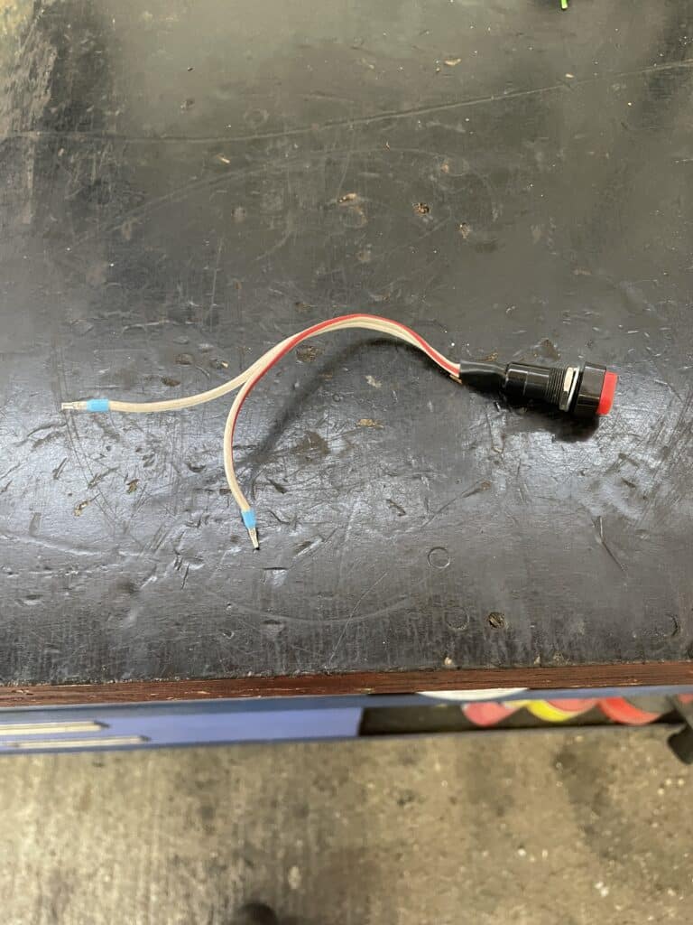
Function and task of an electrical switch:

The electrical switches in a car are essential components of the vehicle system that play a central role in the operation and functionality of the car. These switches allow the driver and passengers to control various electrical components and systems in the vehicle, such as the lights, entertainment system, air conditioning, windows and more. Each switch in a car is specifically designed to perform a specific task by closing or opening a circuit when pressed, thereby activating or deactivating the corresponding function.
The correct operation of these switches is critical to the safety, comfort and overall performance of the vehicle. A faulty switch can not only cause inconvenience by preventing certain functions from performing, but in some cases it can also pose safety risks, for example when it comes to lighting or warning signals. Therefore, the ability to locate and inspect a damaged switch is an important skill for vehicle owners and technicians to ensure that all of the vehicle’s systems are functioning optimally.
Checking an electrical switch:
Visual visual inspection of a switch:
- Tools/aids: occupancy plan/operating instructions, flashlight
- Testing: In order to determine whether a switch is defective during a visual test, its position must first be located according to the assignment plan or the operating instructions. The switch should then be visually inspected using a flashlight. Pay particular attention to whether there are any signs of wear, damage or wear on the contacts or the switch housing. It is equally important to look for any discoloration or signs of overheating, which could indicate that the switch is internally damaged and may not be working properly. This visual inspection can provide initial indications of problems that require further diagnosis or switch replacement.
Functional test of a switch:
- Tools/aids: assignment plan/operating instructions, multimeter
- Test: With this test you can use the multimeter to check whether the switch has electrical continuity when it is pressed, i.e. whether it switches the current through.
To do this, the multimeter must be set to resistance Ω or to the continuity test. In the next step, the two terminals of the switch that are responsible for switching through
must be determined. Now connect the multimeter to the two PINS/terminals. If the switch is not pressed, “OL Open-Line” must now appear on the multimeter display; if the switch is pressed, a low resistance value (0-1 – 0.5 Ω) must be displayed or the multimeter will start to beep.

